Near-Future Pose Estimation of an Autonomous Car Using AprilTag
Originally posted on April 30, 2019 on Github: https://github.com/mlab-upenn/future_pose_estimator.
ROS package that predicts near future pose (up to 1 second) for F1/10th car in front using an April Tag. Written by Christopher Kao for EAS 499 engineering senior thesis in Spring 2019. Advised by Professor Rahul Mangharam and Professor Camillo J. Taylor.
Want a quick overview? Watch this video showcasing the results:

Summary
The goal of this ROS package is to reliably predict the near future pose of a F1/10 car that is in front of our F1/10 car. Specifically, this package returns the estimated pose of a car 1 second in the future. It provides 10 predictions: for 0.1 second in the future, 0.2 seconds, ..., up to 1.0 seconds in the future. The algorithm used by this package requires a number of pieces of information in order to work correctly.
- lidar scan over the /scan topic
- pre-known map of the world in which the car is driving
- image_raw images coming from a USB webcam facilitated by the ROS usb_cam node
- a set of waypoints that represents the general path that the car is expected to take around the race track map

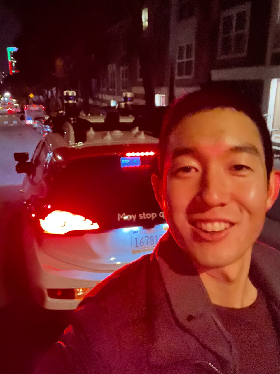
In the image above, notice that there are 2 F1/10 cars. The car behind with the Logitech C910 usb webcam is the car that is running this ROS package. The car in front has an AprilTag of width 10.85cm mounted on its rear.

This is a close-up image of the Logitech C910 USB webcam.
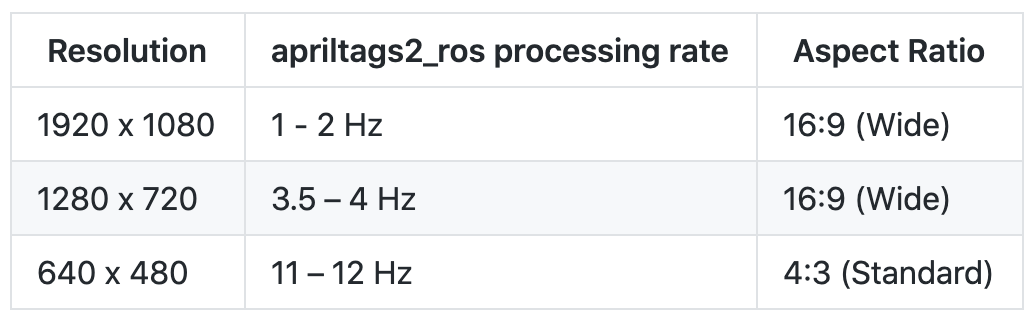
Although the webcam supports up to 1920x1080 resolution at 30Hz natively, from my tests the highest usable resolution is 640x480 which the apriltag_ros package can process at around 10-12 Hz. A higher resolution such as 1280x720 is unusable for our purposes of near future pose estimation because the apriltag_ros package can only process 720p images at around 4Hz. For 1080p images, the speed is even slower, at around 1-2Hz.

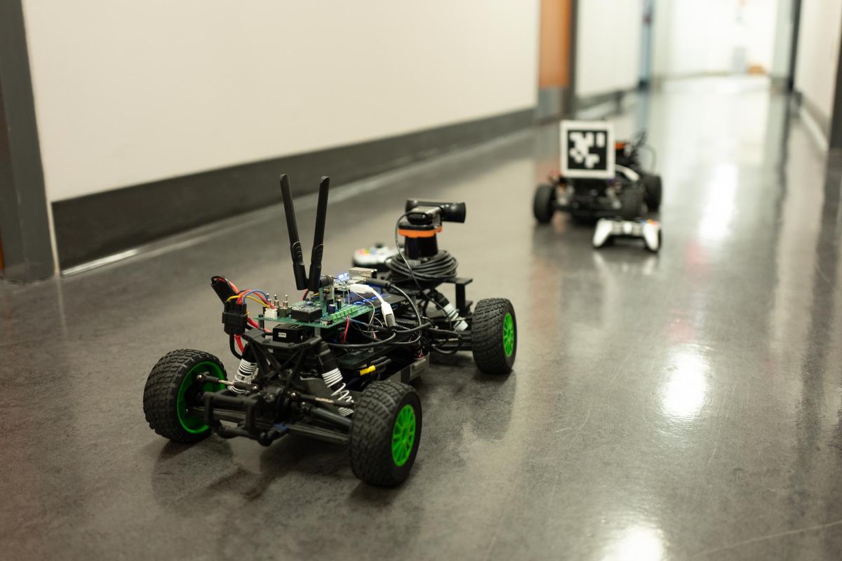
This image above showcases the hardware on the F1/10 car. Going from left to right, the green board is the power board which regulates power from the Traxxas LiPo battery to the Jetson TX2 computer (in blue), the Hokuyo 30LX lidar (black and orange on the right), and VESC (occluded since it is "inside" the car). There are also 2 USB 3.0 hubs which allow for accessories which communicate with the VESC, Hokuyo lidar, Logitech C910 camera, joystick, and keyboard and mouse when plugged in. Also note that on the blue board on the left there is a 64GB microSD card which is important for saving bag files. A simple 3 minute bag file takes up over 4GB because of all the images that are saved, even though they are at a relatively low resolution of 640x480.
Instructions for installing and using this package
Assuming that you have ROS Kinetic installed already, do the following:
- Git clone the mlab-upenn/f110-upenn-course repository (which I was one of the co-contributors for): https://github.com/mlab-upenn/f110-upenn-course
- Follow the README instructions in the f110-upenn-course repository to install the required ROS package dependencies.
- This repository requires the particle filter from MIT-racecar, instructions to install are here: https://github.com/mlab-upenn/f110-upenn-course/tree/master/algorithms/particle_filter.
- This package requires the apriltag_ros repository which is located here: https://github.com/AprilRobotics/apriltag_ros. Git clone this into the /algorithms folder which you will see inside the f110-upenn-course repository which you have cloned.
- Then, git clone this repository into the /algorithms folder. You should now see a folder called /future_pose_estimator.
- You will then need to sudo apt-get a few packages that this package depends on for usb cam images.
sudo apt-get install ros-kinetic-usb-cam ros-kinetic-camera-calibration
At this point, navigate to the root of your workspace (ws) ROS directory, and type catkin_make. This may take a few minutes to build. If you see any errors, there may be other ROS packages that you need to install. The error messages will give you hints as to what you need to install. The command to install will be of the form sudo apt-get install ros-kinetic-[insert package name with hyphens]
Downloading the Bag File
I used Git LFS (Large File Storage) to host a 2GB bag file which is located in the /bags folder titled "two-cars-levine-loop-bad-lots-of-stops.bag". You may wonder why this title for the bag. I purposely chose to use the bag with lots of stops so that we can get more tests of edge cases as the car drives around the Levine 2nd floor loop. You will need to run the following commands in the repository to get this bag file.
First, install git-lfs from https://git-lfs.github.com. Then navigate to this repository on your computer.
git lfs install git pull git lfs fetch
Now the 2.03 GB size bag file should show up in a folder called /bags.
Printing your AprilTag
You will also want to print your own AprilTag. You can do this with the id0 pdf AprilTag found in the /apriltag-printout folder in this repository.
Description of package files
These are the descriptions of the folders in this future_pose_predictor package. Here is a video that walks through the code and package structure: https://www.youtube.com/watch?v=SwMhvUBpBnY.
/config
- Contains camera calibrations for the Logitech C910 webcam at various resolutions. The one that is used in the launch files of this package is the logitech_c910_calibration_640x480.yaml file.
- Also contains rviz_custom.rviz, which is a custom Rviz configuration which showcases the map, laser scans, image raw, AprilTag processed image raw, and much more.
- settings.yaml is a modified version of a file from the apriltags2_ros package. This is an input parameter to the apriltags2_ros package in the launch file. Here I have told apriltags2_ros to only look for tag36h11 family, which is the default family for AprilTag. I have also asked apriltags2_ros to publish the transform from the camera to the tag. I have not changed the remaining parameters.
- tags.yaml contains the list of April Tags that should be recognized. Here I have only specified that one tag be identified, which is tag with id 0. I made this conscious decision because I am assuming a race with only 2 cars, and that we only need to detect the specific tag on the back of the car in front. Note that this file also needs to specify the size of the tag, which is 0.1085 meters. If you print your AprilTag at different sizes, you can. Just make sure to update this file. This file is specified as a parameter for launching apriltags2_ros in the launch files in the /launch folder.
/launch
- detect_apriltags.launch opens Rviz and shows the detected AprilTag, as well as the transform from the camera to the AprilTag.

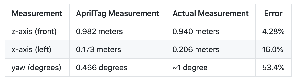
This screenshot above represents what you would see when running "roslaunch future_pose_predictor detect_apriltags.launch" in the terminal. On the right, you see an Rviz window. The large window on the right represents the transform from the camera to the id_0 AprilTag. On the left, notice Raw Image window (the image on top) which is taken in the mLab and shows the id_0 AprilTag on the left side. Below that, the ProcessedImage is the same image but with highlighted boxes around the AprilTag. On the far left of the screenshot, notice a stream of xyz AprilTag predicted positions and yaw. AprilTag originally outputs the xyz and quaternion, but because we are dealing with F1/10 cars which lie in a 2D plane, we only need the yaw. Looking at the most recent output on the bottom of the terminal window, the apriltags2_ros library computes that the AprilTag is 0.165 meters to the left, 0.173 meters down, and 0.982 meters in front. It also predicts that the yaw of the tag relative to the camera is 0.466 degrees. I then measured the actual distance and yaw angle. Here is what I saw:

- bag_future_pose_estimation.launch runs the near future pose estimation algorithm on a bag file. The bag file contains the laser scan, image raw stream, camera calibration, and vesc odometry which is used by the particle filter. Note that once the bag file starts playing, it takes around 5 seconds for apriltags2_ros to begin publishing transform messages, so you will want to press the space bar in the terminal to pause the bag file for a few seconds, so that the particle filter does not lose its localization. Here is a video of what you will see when you run this launch file: https://www.youtube.com/watch?v=HVJxHHeB9qo.
- future_pose_estimation.launch is nearly identical to bag_future_pose_estimation.launch. The main difference is that instead of playing back from a bag file, the launch file activates racecar teleop.launch which allows the car to be driven live. When you are driving the car live, you may want to see what the car is seeing, with which you can set up VNC. Instructions are in this reference guide which I co-wrote: http://f1tenth.org/build.html#settingupvncserveronjetson.
/maps
- Contains the map for Levine Hall 2nd floor, which represents a loop around the mLab. ROS standard is to contain both a .pgm file and a .yaml file, which specifies how the .pgm pixels correspond to actual distances in meters. I created this map using an architectural floor plan of the building, and I drew it in Photoshop.
/src
- Contains many Python files which do various tasks.
- future_pose_estimator.py is the file which contains the main algorithm. It subscribes to the AprilTag published transform and also uses the set of waypoints, in order to predict where the car will be in the near future. It publishes a MarkerArray which contains 10 Markers, which represents predictions for the car in the future in 0.10 second increments.
- front_car_pose_saver.py is used to save the "actual" locations of the car in front as a csv of waypoints.
- predicted_poses_saver.py is used to save the MarkerArray locations of the predictions of the car in front as a csv of waypoints.
- quaternion_to_yaw.py is used by detect_apriltags.launch in order to output to the terminal screen the xyz position and yaw of the detected AprilTag.
- visualize_actual_poses.py is used to plot in Rviz as a MarkerArray the entire sequence of actual poses of the car in front over an entire loop.
- visualize_markers.py is used to plot the waypoints.csv file which is an estimate of the general path that any car would take in the race track.
- visualize_predicted_poses.py is used to visualize the predicted poses in Rviz as a MarkerArray the entire sequence of predicted poses of the car in front over an entire loop.
/waypoints
- levine-waypoints.csv (yellow in Rviz) is the set of waypoints plotted in Rviz representing generally the path a car would take if it followed almost dead center between the walls around the race course.
- actual-poses.csv is a set of waypoints plotted in Rviz representing actual poses of the car in front
- predicted_poses.csv is a set of waypoints plotte din Rviz representing predicted poses of the car in front
Experimental Results
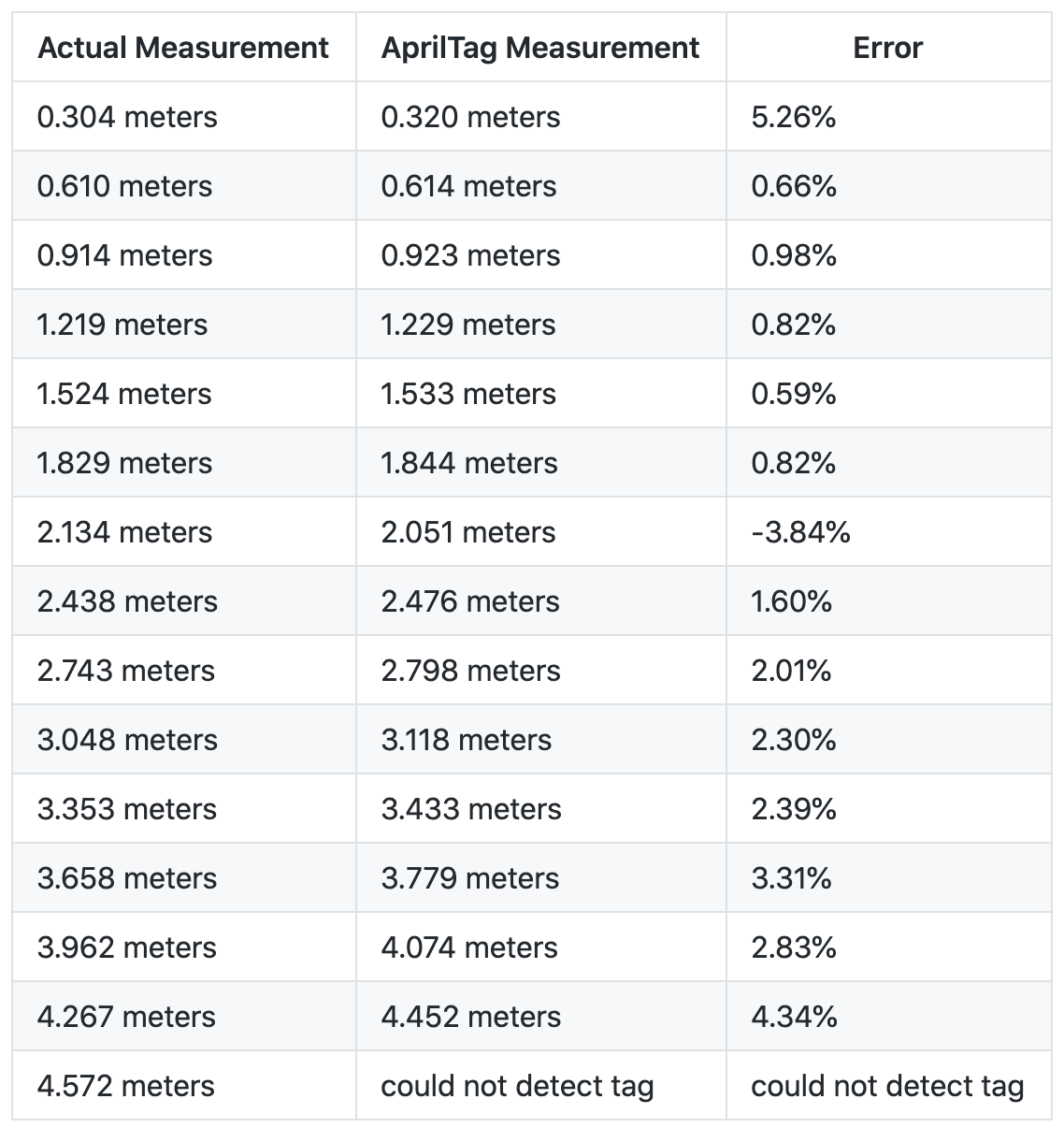
Experiment 1. Accuracy of raw AprilTag measurements

Experiment 2. Accuracy of raw AprilTag measurements while car is moving backward
Video Link with sychronized dual videos:
Table below has values which are taken at equidistant steps, 10 frames apart, for 24fps videos.
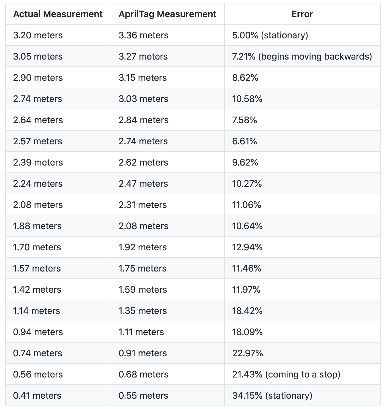
The results here look a lot worse than I thought they would be. The error seems to grow larger as the car moves backwards closer to the camera. The reason is likely because of some type of delay in computing the AprilTag measurement, which results in a pretty constant difference in actual vs AprilTag measurement of around 0.15-0.20 meters. Here it seems like that the AprilTag is taking around 10 frames (at 24 frames per second) to process, hence if we were to move all the AprilTag measurements earlier by 10 frames, or 0.42 seconds, the measurements would line up. This graph is insightful because it shows us an AprilTag processing delay of around 0.42 seconds. I don't think there are any confounding variables with Experiment 1 because Experiments 1 and 2 share the same setup, and were recorded only minutes after each other. Another reason for the roughly 0.42 second delay is that the AprilTag is also processing at around 10Hz, around 0.1 seconds, so it may also take 0.1 seconds before getting the next AprilTag measurement.
Notice that if we shift the AprilTag measurements such that they are 10 frames earlier (0.42 seconds earlier), the error is in line with the results of Experiment 1 when the AprilTag was stationary.
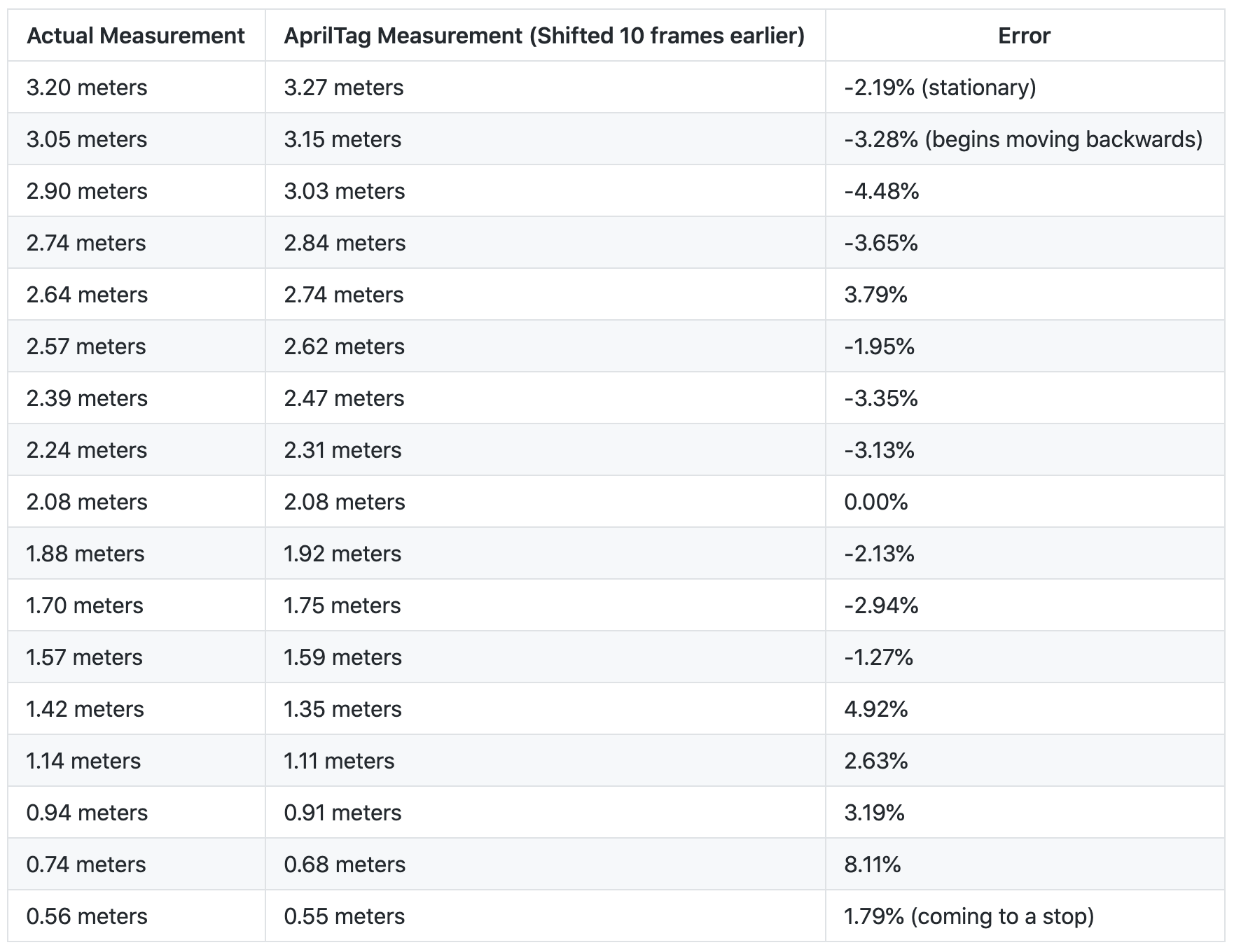
Notice that here the error measurements are much more in line with the results of Experiment 1 when the AprilTag was stationary. This is evidence that the AprilTag measurements are indeed delayed by around 10 frames, or around 0.4 seconds. This delay could result from printing the AprilTag measurements in the terminal window, since it is known that Python print statements - especially when printing a lot of statements - slows down the code.
Experiment 3. Accuracy of near future pose predictions

This is a color coded image comparing the actual versus predicted path.
- RED: Actual Pose of the car in front (saved waypoints around the entire loop)
- GREEN: Near future pose prediction algorithm's current prediction for where car will be 1 second in the future
- BLUE: Actual Pose of the car (generated by saving all of the GREEN pose estimates over an entire loop). Note that even though blue in this case represents the actual pose of the car, it isn't the actual pose because it is still relying on AprilTag measurements, which as we showed in Experiments 1 and 2, has around 5-10% error. Moreover, the blue dots also relies on the particle filter measurement for the location of the car with the camera, based on lidar measurements, which also has some error. = YELLOW: This is just a set of waypoints that is used by the near future pose prediction algorithm to know the general direction that the car should be going in the map.
Notice that in general, it is good if RED and BLUE overlaps (because it means that predicted path was similar to actual path), and bad if RED and BLUE do not overlap. On straightaways there is a lot of overlap. On turns, there is less overlap. Images below will analyze the results.
Here is a video of the car going around the track: https://youtu.be/5Zgwl0yWQF8. I tried screen recording on the F1/10 car's Jetson TX2 using the Kazam software, but it only recorded at less than 1 frame per second because of the simultaneous computing resources used for particle filter, AprilTag processing, image processing, etc. Therefore, I recorded this with my camera so that you could see the actual frame rate.
Case 1. Going straight while near the right wall

This is a case where the car is going straight but it is located closer to the right wall. Notice that both cars here are moving from right to left, in a counter-clockwise fashion around the map. other_base_link represents the actual location of the car in front. This location of other_base_link is a transform between the other_base_link and map frames. Notice that the green dots represent where at this point of time, where the algorithm predicts the car will move. This prediction is clearly wrong because while the green dots bank left relative to the car, the blue dots (which represent the actual pose of the car) bank slightly towards the right. The predicted pose banks towards the center waypoints (represented in yellow). As we follow the blue dots which gradually get closer to the right wall, notice that at every time step the predicted pose is towards the left to get to the center of the path, which is constantly off until finally the car banks towards the left to initiate a left turn.
Case 2. Car preparing for a left turn
Here, the car is approaching a left turn. If you watch the video linked above, you'll notice that the car stops because I had to adjust the AprilTag on the back. I decided to leave this in because it could simulate a car which may suddenly stop, and offers a test case for if someone walks onto the track. Notice that for as far as a meter before the car actually makes a left turn, my algorithm predicts that the car will begin turning left. All of these are, for the most part, incorrect. If you look at the blue dots, notice that the car actually turns later than it is predicted to. This could be due to the farther lookahead distance of 2 meters set in the pure pursuit prediction aspect of the algorithm. Setting a shorter lookahead distance may partially alleviate this problem for turns.
Case 3. Car making left turn later than expected

Here, the car finally makes a left turn, later than expected. Notice the trail of red paths from earlier predicting that the car would make a left, when instead the car continued moving straight. When the car finally does make the left turn, the AprilTag later falls out of frame, which is why there is a discontinuity in the blue dots, which represents where the car actual went.
Case 4. Car going down straightaway

Here the car is moving from top to bottom of the image. other_base_link represents the car that we are predicting the future pose of. Notice that the green dots overlap the blue dots pretty well. This is a good thing. Because the car is generally in the center of the track, the algorithm predicts that it will follow the yellow dots (the waypoints which I generated to track the center of the race track). Notice also that as the blue dots oscillate slightly from right of center to left of center, the red dots also track this general motion. This is due to my algorithm taking into account the current yaw of the car and using a linear model that projects forward the car's current motion.
Case 5. Car initiating a left turn

Here the car is initiating a left turn. The predicted trajectory at this point (in green) does not overlap with the actual future path of the car (in blue). Instead, the car continues straight for a bit more and makes a wider left turn. With future time steps, however, the algorithm adjusts and eventually predicts the correct trajectory. There is a chance that the car in front may have been trying to make a left earlier, but because of dynamics of the car such as drift, the car ended up making a wider turn. It is also possible that due to the roughly 0.4 second delay of the AprilTag, as was quantitatively measured in Experiment 2, perhaps the car is actually further ahead, and hence it is tracking the blue dots. I tried to analyze the videos, but because it is a 2D image with the car far away, it is difficult to judge the depth of the car. More analysis can be done on this in future work, for those who continue this project.
Case 6. Car makes left turn late

It turns out that the car makes the left turn pretty late. Here, the prediction is accurate. The green dots follow the blue dots. Although we can't see the blue dots continuously here (because the car's AprilTag quickly falls out of frame of the camera), it's clear that the green predicted pose tracks the blue actual pose. Note that if we were using a simpler algorithm in this case, such as a linear model which just projects forward the car's current orientation, the resulting predicted pose would have been a straight line through the right wall.
Case 7. Car going straight

This looks pretty accurate. Blue dots overlap with red dots.
Case 8. Car making third left in the map

This left turn looks pretty accurate. The blue dots track the red dots. Notice that there are elements earlier though where red dots predicts that the car should turn earlier, but the car did not turn that early.
Case 9. Car veering back towards center from right

Here the car is accurately predicting that it will veer back towards the center.
Case 10. Edge case where car wants to loop around

The green dots here indicate the algorithm predicts that the car will go into the wall? You must be wondering what is going on here. This is an edge case. Because my algorithm uses pure pursuit as part of its weighting process, and because pure pursuit thinks that the closest yellow point is the one behind the car (as opposed to the one in front of the car), the car attempts a hard right turn in order to loop back to the point behind it. This is only a momentary problem, because as soon as the car advances forward another few centimeters, it picks up the point in front and makes an accurate prediction. I thought it would be important to explain this edge case here for the accute readers who picked this up.
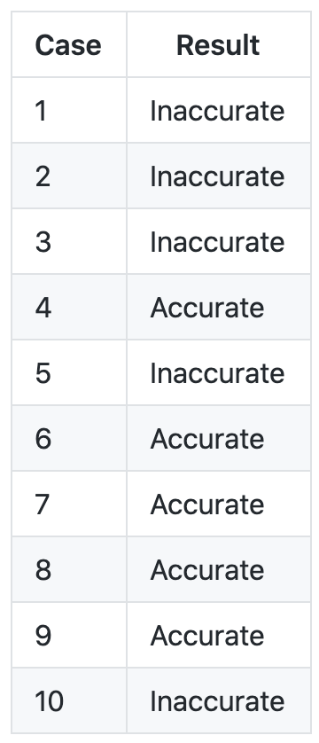
To summarize Experiment 3, here is a table of which results were good (predicted path tracked actual path) and which were bad (predicted path did not track actual path).
Description of algorithm
In general, the algorithm is a weighted average between a linear model and a pure pursuit model. The linear model takes into account the car's current yaw (orientation) and position, and projects it forward in a straight line. The pure pursuit model predicts that the car will generally follow the set of yellow waypoints. From 0 to 1 second into the future, in the immediate short term (think 0.1-0.4 seconds), more weight is placed on the linear model. As projected future time increases, more weight is placed on the pure pursuit model. The logic here is that in the immediate future, the car cannot do much to change its inertia and orientation. But further in the near future, the car will generally follow the direction of the track.
Here is the math equation:

For additional details and the thought process behind this algorithm, please reference the full paper I have written which is included in this repository. TODO: When I am done with the paper, include the pdf and .docx versions of it in the Github repository.
How to test on different maps/tracks
Chances are that if you are running this code, you won't be in the same location and will have a different track to run on. If you want to run the code as is with minimal configuration, you can run from the bag file by doing "roslaunch future_pose_prediction bag_future_pose_estimation.launch". If you would like to use your own set of waypoints and map, here is where you would change them.
- In the /maps folder, add your own map.
- In the /waypoints folder, add in your set of waypoints. You can record a set of waypoints while driving your car around your map and using particle filter localization using the waypoint_saver package inside of the f110-upenn-course repository which is linked near the top of this README.
- In the /launch folder, modify the launch file so that you specify the updated map name and the initial pose for the car within the map.
How to set up a different USB webcam
Chances are that you do not have the exact same USB webcam I have which is the Logitech C910. (If you do, hey cheers to you!) Follow instructions from the ROS camera_calibration package: http://wiki.ros.org/camera_calibration.
- You will need to print out a checkerboard pattern, which is linked on the page.
- Mount the checkerboard pattern on a piece of cardboard or equivalently flat, hard surface.
- Run the command described on the website that starts with "rosrun camera_calibration cameracalibrator.py ..." and do the calibration process.
- You will see a screen that looks like this:
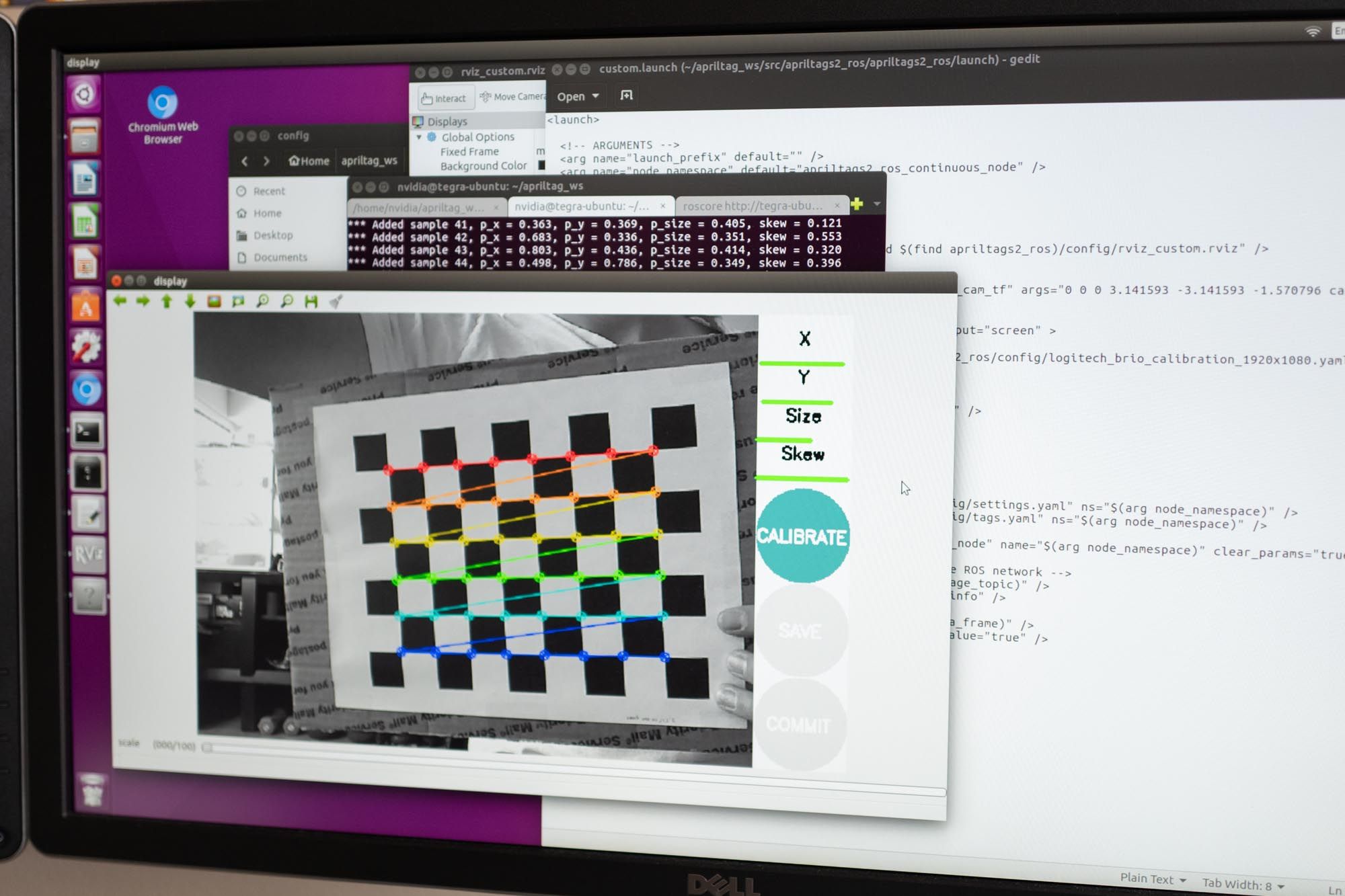
5. Once calibration is complete, find the .yaml file for the calibration and copy it into the /config folder from this repository.
6. You will need to modify the launch files in the /launch folder such that they load your calibration file and also so that the resolution matches your camera.
Opportunities for Improvement
- As you can see with the results above, in around half the cases the algorithm inaccurately predicts the near future pose of the car. The case I see with most inaccurate predictions is when a car goes into a left turn, but ends up turning later. The algorithm predicts that the car begins turning a bit earlier than if it were staying in the center of the track. How might we be able to have an algorithm that predicts that the car makes wider turns? Perhaps playing with the lookahead distance, specifically by setting a shorter lookahead distance for the pure pursuit component of the algorithm, may address this problem. Or you may need to just rethink the algorithm, so that it considers what the car did in the past. Currently the algorithm does not consider past behavior of the car.
- Often times the AprilTag falls out of the frame of view of the camera. Currently my Logitech C910 is set to record at 640x480, which is not a widescreen resolution. This is a 1.33 aspect ratio, whereas typical HD formats like 720p and 1080p are 1.77 aspect ratios. Hence, with the current 640x480 resolution, the AprilTag will fall out of frame when the AprilTag moves too far to the left or right. I did try using 720p, but the problem was that the AprilTag rate was only 4Hz which was unusable, compared to 12Hz from 640x480. I did also try other 1.77 aspect ratios of lower resolution such as 850x480, but any resolution besides 640x480 led to entirely incomprehensible images that were a bunch of random horizontal lines. I think that the resolution is locked at the physical level. When looking at the Logitech C910 website specs, it does list 640x480 as one of the native resolutions. It would be helpful to get some type of webcam that can support lower resolution at wide aspect ratio.
- What happens if our car begins to pass the other car from the side? Then clearly the AprilTag will fall out of field of view. This is arguably the most important aspect of passing where we need to know the other car is. How might this be solved? Could we mount 2 different USB webcams? Do we mount 3 AprilTags on the car in front? One on its rear, and one on each side? Each AprilTag would have a different id and we would hard code the locations of each id relative to that car. Is it even possible to use a 180 degree or 360 degree camera? And process the image in equirectangular format?
Special Thanks
Thank you to Professor Mangharam and Professor Taylor for advising me on my senior thesis. Also thank you to Matt O'Kelly for providing insight into the weighted averaging algorithm used, and for his many calls and Slack messages and in-person meetings since last summer with answering my F1/10 questions.
I spent summer of 2018 learning about F1/10 cars for the first time, while developing a new ESE 680 course on autonomous racing which I assistant taught in fall of 2018. Then in spring of 2019 I worked on this project.